How to Match a Replacement Hose to Your Vacuum Model: A 4-Step Check
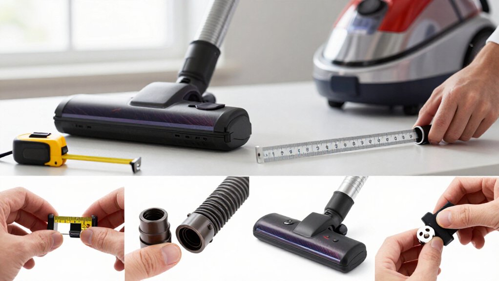
Match a replacement hose in four steps.
First, record your vacuum’s complete model number and measure the old hose end-to-end.
Second, unplug the vacuum, photograph the inlet, and compare its diameter, pins, prongs, and locking features with the replacement.
Third, wipe connectors clean, inspect tabs and seals, then reseat and gently wiggle-test for looseness.
Fourth, test suction at the floorhead and listen for leaks.
The checks below explain storage, failure signs, and final fit confirmation.
Four-Step Fit Verification
Start by identifying your vacuum type—canister, central, upright, stick, or cordless—because each uses different hose lengths, inlet designs, and connector systems. For a central vacuum, lift the outlet flap and measure the inlet opening.
About 2.5 inches (63.5 mm) usually provides universal replacement fit.
Next, inspect the hose-end connection. Match direct-connect designs, which use electrical prongs, with matching contacts. Choose a pigtail design only when your system accepts an end cord; connector presence must coincide.
Then, verify electrical compatibility. Confirm whether the hose and wand are electric, and ensure the wand neck and wiring belong to the powerhead family.
Finally, compare the critical interface physically: diameter, prong or pin layout, and locking fit. Don’t order until every feature matches your vacuum’s inlet and tooling.
Gather Model Number, Tape
First, locate the vacuum’s model plate on the motor housing, underside, behind the dustbin, near the battery, or on the base, and record the complete alphanumeric model number, including every suffix. Photograph the plate, then transcribe its serial number, manufacturer, and date code when available. Check the hose or connector for an OEM part number, and cross-reference it with the manual, exploded parts diagram, and manufacturer’s compatibility list. Production revisions can alter fittings, so note serial ranges, regional variants, and exclusions.
- Mark a removable strip of tape with the model and serial numbers.
- Add measured ID, OD, and hose length in inches and millimeters.
- Record connector style, cuff dimensions, and photo filenames.
- Retain the labeled old hose until the replacement fits and performs correctly.
Step 1: Unplug Vacuum Before Inspection
With the model and part information recorded, unplug the vacuum before removing or inspecting the hose or wand. This prevents contact with live electrical connections, which matters especially when you’re checking an electric hose, powered wand, or powerhead. If the vacuum has a cord, disconnect it from the outlet and secure the cord away from your work area.
Remove the hose from the vacuum inlet and every tool connection point. Compatibility depends on a secure fit at every interface, not just the inlet. Once disconnected, inspect labels on the vacuum and hose ends for model or part identifiers.
Then measure outlet and port diameters, including a 2.5-inch central-vacuum outlet hole. Record each measurement in millimeters and inches, and keep the components unpowered during inspection.
Step 2: Photograph the Connection Port
Photograph the exposed connection port after removing the hose, and capture enough detail to identify its shape, diameter, and electrical features. Take one straight-on image to show the opening and overall geometry, then take an angled image to reveal depth, molded ridges, seals, or recessed areas.
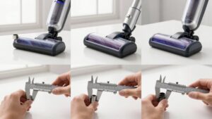
Place a ruler or calipers in the frame, and keep the scale aligned with the port so you can record its actual diameter. Named hose sizes often differ from real outer diameters, so rely on these measurements when comparing replacement cuffs and adapters.
For a central vacuum, photograph the wall inlet or outlet flap, showing its opening and whether it appears direct-connect or pigtail style. If the port supplies power, include wiring points or switch and connector details.
Step 3: Inspect Connector Pin Layout
Before ordering a replacement, disconnect the hose and wand, then inspect both the vacuum-side inlet and hose-side connector for electrical pins or prongs.
Count the pins or prongs, record their positions and spacing, and compare them with the vacuum inlet’s arrangement. Measure the connector interface, including port diameter and, where applicable, prong geometry. Don’t rely on nominal hose size; manufacturers can vary outside diameters and connector dimensions under the same label.
If the connector carries power, verify that each contact aligns with its matching socket so the powerhead or tool wiring can operate safely. If you see a two-prong direct-connect design or an electric-cord pigtail, match that exact style. Record nearby model labels and take a close photo before ordering to verify exact series.
Step 4: Test Wand Swivel Fit
Does the wand swivel smoothly without binding or excessive wobble? With the vacuum unplugged, remove the hose and wand, then turn the wand at its connection point. Confirm the joint moves freely and maintains resistance without floating. Check the locking or neck mechanism where the wand seats in the powerhead or tool; it should line up securely and seal without play that could cause leaks.
Reconnect the assembly and repeat the swivel test through its normal range. Watch for pinched wiring, on electric sets, and stop if the cable pulls or kinks. Inspect the swivel region for wear marks, cracked strain reliefs, or debris. Ensure rotation stays secure and the airflow passage remains unobstructed. If movement binds or fit feels loose, don’t use it.
Step 5: Measure Length Against Original
Measure the original hose end-to-end, then compare that measurement with the replacement’s actual packaged length, not just its advertised size. Check whether it can reach the farthest task; a 10-foot Shop-Vac hose won’t replace a built-in garage hose measuring about 50 feet. Measure the replacement as supplied, because packaging labels may state a nominal length that differs from usable length.
Plan the route before you order. Add clearance for bends, turns, and necessary slack; a straight-line match can become too short when routing around equipment. Record the original length alongside its outside and inside diameters. For example, note approximately 40 mm OD and 32 mm ID. Length confirms reach, but it can’t correct a dimensional mismatch at the vacuum or tool connection for reliable reach.
Step 6: Wipe Dust From Connector
Remove the hose from the vacuum, then wipe dust and grit from both connector ends, especially the final 2 cm where debris can prevent a snug, airtight seal. Use a clean, dry cloth; don’t introduce moisture into the fitting. Wipe around electrical contacts on an electric hose, removing dust that could impair continuity even when the mechanical fit appears correct.
As you clean, inspect both fittings for abrasions, cracks, or peeling. A longitudinal crack near an end can spread and become a complete hole. Afterward, perform a dry fit with the vacuum off. Confirm the connector locks securely; it shouldn’t wobble or back out with light hand pressure. If it doesn’t seat evenly, stop and clean the surfaces again before evaluating compatibility carefully.
Test Suction at Floorhead
With the floorhead disconnected, switch on the vacuum and listen for a high-pitched hiss that indicates an air leak. Run an ear test while moving the hose slowly between your fingers.
A sharp hiss identifies a likely leak; this method locates about 80% of leaks in under two minutes.
If you hear noise, inspect the final 2 cm at each hose end first. Then check natural bends and weak areas roughly 30 cm from the tank connection, where repeated flexing can open gaps.
To confirm a subtle leak, apply soapy water while suction runs. Bubbles mark escaping air. Switch off the vacuum, wipe away solution, and dry the hose thoroughly before reconnecting the floorhead.
Compare suction at the floorhead after reassembly to verify performance.
Inspect Cracked Locking Tabs
Before replacing the hose or wand, inspect the connector’s locking tabs for cracks, splits, or whitened stress lines, especially within the last 2 cm of each fitting.
Check both hose-end and vacuum-side tabs, where damage can spread from the fitting. Reseat the connector, then perform a gentle wiggle check. If it feels loose, shifts under light pressure, or backs out unusually easily, suspect failed retention and an air leak.
| Inspection | Finding | Action |
|---|---|---|
| Tab surface | Crack or split | Replace connector |
| Stress line | Whitening | Reject fitting |
| Reseated joint | Loose movement | Stop installation |
| Seal path | Air leak risk | Verify replacement |
Don’t force cracked connection: damaged tabs won’t maintain seating or air/debris path. Replace the connector side, the hose end or tabbed piece, instead of relying on a compatible fit.
Store Hose Without Kinks
Once the connector passes inspection, store the hose in loose coils or large hanging loops to prevent sharp bends, especially at the tank end. Before storage, remove blockages and let the hose dry completely, particularly after a soapy-water leak test, because residue can stiffen the material and increase cracking risk.
Keep it away from heavy loads in storage bins; crushing promotes holes and longitudinal cracks. Don’t tightly fold it in a bag or container.
Inspect the natural bend area about 30 cm from the tank, where repeated flexing can initiate cracks. Check the final 2 cm at each fitting end for distortion, splits, or abrasion, since these areas are critical for leaks.
Use a support that preserves the hose’s relaxed curve during storage periods.
Conclusion
Once you’ve completed these checks, you can match a replacement hose with confidence. Confirm the vacuum’s model number, connector geometry, pin layout, and locking features before ordering. Reconnect the hose only after you’ve removed dust and inspected for damage.
Then test suction at the floorhead. If the fit is loose, forced, or electrically mismatched, don’t use it. Store the approved hose in a wide, relaxed curve to prevent kinks and preserve long-term performance over time.