
Robot Mop Dock Refill and Drainage Setup Guide
You’ll plan and clear space behind the dock, measure drain and water paths, and gather adapters, 90° fittings, clips, and check valve. Leave a few inches for trim and cable access. Convert your supply to the dock’s 1/2″ G inlet using 3/8-to-1/2 or 3/8-to-3/8 adapters. Route a 1/4″ feed to the solenoid, and install the 3/8″ drain with the check valve arrow pointing down and a locking clip.
Power up, bleed air, and test for leaks and steady flow. Continue for step-by-step assembly, leak checks, and troubleshooting tips.
Quick Overview
- Leave clearance behind the dock for plumbing, electrical access, and to prevent kinks in supply and drain lines.
- Use proper adapters (3/8-to-1/2 G or 3/8-to-3/8) and 90° fittings to match home supply routing and tight spaces.
- Install the 3/8 drain with the check valve arrow facing down. Push fully and secure with the locking clip.
- Route a 1/4″ supply line to the solenoid; seat fittings fully. Then test slow water-on for leaks and pressure issues.
- Power up and run a self-test and a focused refill cycle. Bleed air until steady flow and inspect for leaks with paper towels.
What You’ll Need: Parts, Tools, and Site Measurements
Ready to get started? You’ll need specific parts and site measurements to avoid surprises. Collect the kit components: water supply line (G to G 12 in), solenoid, 90° waterline adapters, GT T fittings, 3/8 drain line with RORO tubing, check valve with labeled arrow, protective tubing wrap, and the drain line filter (wash/replace).
Bring adapters for the 1/2 inch G inlet if you must convert 3/8 to 1/2 inch G or 3/8 to G half inch for solenoid routing.
Tools: basic wrench set, locking-clip pliers, tubing cutter, paper towels for leak testing. Measure: unit footprint (~10 5/8″ x 8 1/2″ x 2 1/4″), available clearance behind unit for drain projection, and expected tubing pressure (supports up to ~60 PSI for RO).
Note unrelated topic: don’t mix in plan-space tools here. Factor pricing considerations when sourcing adapters or replacement filters to stay within budget.
Plan Space and Tools: Clearance, Drain Path, and Power
How will the dock fit into the space you’ve allocated? Start with space planning: Leave clearance behind the base for plumbing and cables so supply and drain lines don’t kink. Measure routing paths for the drain and water lines; allow a few extra inches where lines may protrude and plan to trim later for a snug fit against the wall.
Create a clear tool inventory before you begin. Include fittings for 1/2 G inlet routing, 1/4 supply elbows or 3/8–1/2 adapters, locking clips, and a check valve oriented with its arrow pointing down on the 3/8 drain line. Account for a maximum drain run height of 2–3 feet when laying out the route to the nearest suitable drain.
Verify power access and that the USB-C/exposed connector for integration remains unobstructed. Keep adequate clearance around back-panel entry points so you can secure lines and test operation without moving the dock repeatedly.
Prepare Water Supply: 1/2 G Inlet, Pressure Spec, and Adapters
Want the water hooked up cleanly and leak-free? You’ll work with a 1/2 inch G threaded inlet on the dock. Most installs need adapters to join 3/8 inch compression lines to the 1/2 G fitting; use a 3/8-to-1/2 G adapter or 3/8-to-3/8 adapter depending on your existing supply.
90-degree fittings are provided for tight routing; pick the orientation that avoids kinks and strain. Route a quarter-inch supply line directly to the solenoid when specified, and attach its wiring so the controller can power the valve. Confirm your home pressure matches the device spec before finalizing connections. Excessive pressure can stress fittings.
During initial setup, turn water on slowly and check every joint with a paper towel for moisture. Tighten only as needed; over-tightening can damage threads. Ignore unrelated topics or off-topic ideas that don’t affect fittings, flow, or pressure. Follow these steps and you’ll have a reliable, leak-free refill supply.
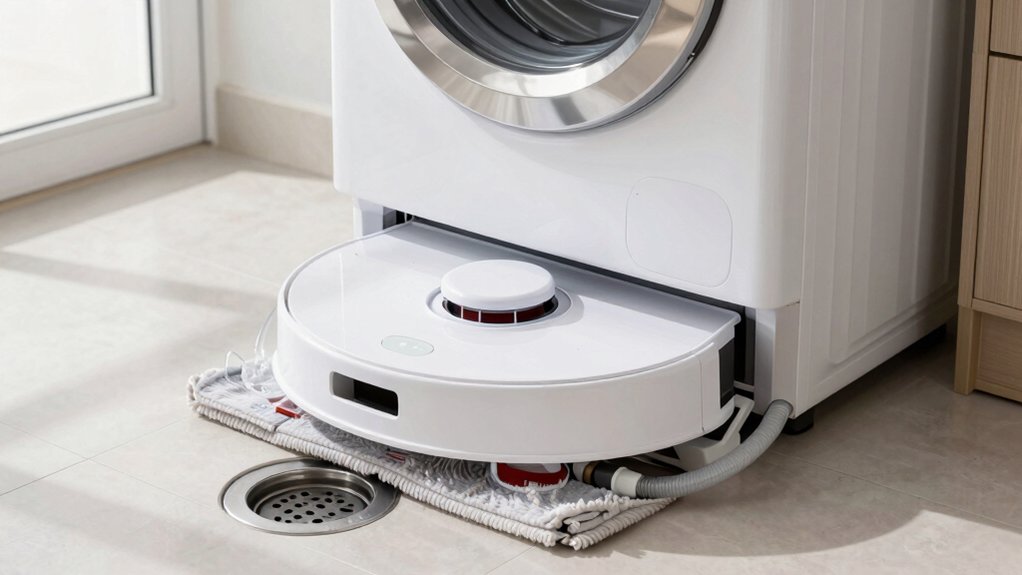
Assemble and Secure Drain: 3/8 Line, Check Valve Orientation, and Clips
With the refill supply routed and pressure verified, you’ll assemble the drain line next to keep waste water flowing reliably. Install the check valve on the 3/8 drain line with the arrow facing down to maintain correct drain orientation; this prevents backflow into the dock. Push the 3/8 line fully into its connection until it stops. Then give a firm tug to confirm it’s seated.
Attach the small locking clip immediately to prevent accidental removal after that initial connection. If the drain line protrudes, trim it so the tube sits flush or against the wall while leaving minimal room behind the unit for movement. After routing, secure the line with a larger locking clip for final clip security and neat routing.
When tying into a building drain, use the provided 90° fittings where needed to avoid kinks and preserve flow. Test drainage visually before moving to plumbing connections.
Connect Plumbing to Robot Dock: Solenoid, RO Line, and Base Feed
Before you connect anything, shut off the main water and verify the 1/2″ G threaded inlet is ready. Then route the 3/8″ RO line through any required 90° adapters so it reaches the solenoid cleanly while the 1/4″ supply line feeds the solenoid itself. Next, attach the solenoid, making sure fittings are tight and the 1/4″ line seats fully into the solenoid input.
Route supply and drain lines through the base holes to keep an accessible path and allow future re-routing. Install the 3/8″ drain line to the base station using the provided 3/8″ adapter; trim any excess that protrudes behind the unit for a neat fit. Push the check valve fully in on the left side, set valve orientation arrow downward, and secure with the larger locking clip.
Confirm all threaded joints are sealed. Plan for drainage planning by leaving slack and stable routing so automatic supply and drainage cycles run without strain or kinks.
Power Up and Run Self‑Test: Bleed Air, Check for Leaks, and Mop Wash
Now that your plumbing and fittings are secured, power up the dock and start the device’s self-test while staying nearby so you can respond if the cycle halts. Begin with a focused self-test bleed: run the refill cycle until steady water flows, venting trapped air from lines and fittings. If you hear sputtering or see intermittent flow, pinch and open lines or use the manual bleed point until bubbles stop.
Next, perform systematic leak checks. Lay paper towels along the water, drain, and solenoid connections. Then, watch during and immediately after the test for dampness or drips. Confirm the drain line check valve arrow points downward, push the line fully home, and lock the clip so it won’t withdraw during operation.
Finally, initiate mop wash from both the app and the dock. Expect a 1–2 minute delay depending on control source. Observe mop responsiveness and note any timing differences for later adjustment.
Troubleshooting: Leaks, Weak Drain Flow, and Mop‑Wash Delays
Having trouble with leaks, weak drain flow, or mop-wash delays? Start with leak prevention: run a paper towel along water and drain lines while a test cycle runs, tighten adapters (3/8 to 1/2 inch G, 1/4 inch supply elbows), and re-seat collars and clips until towels stay dry.
Confirm the drain line check valve arrow faces down; the larger locking clip is fully engaged.
For flow optimization, keep the drain path within the wall limit, maintain a consistent pitch, and remove kinks or sharp bends that impede gravity flow. If drain flow is weak, lengthen the run only as allowed and re-check pitch.
If mop-wash delays occur, expect a 1–2 minute startup lag for manual dock washes. Compare app-initiated versus dock-initiated cycles for responsiveness. After initial testing, vent any air trapped in lines to complete a successful self-test and establish consistent drainage cycles.
Frequently Asked Questions
Can I Use Softened Water or Will It Damage the Dock?
You can use softened water; it won’t damage the dock. It reduces mineral buildup that can clog valves and nozzles. Softened water may make cleaning solutions foam differently; thus, follow your manufacturer’s recommendations for dilution.
Rinse filters and replace cartridges per schedule to avoid salts concentrating. If your dock advises against softened water, use distilled or filtered water instead. Regular maintenance prevents issues from residual minerals.
How Often Should I Replace Check Valves and Fittings?
You should replace check valves and fittings every 3–5 years or sooner if you spot leaks, poor sealing, or reduced flow. Perform periodic inspection at least annually to catch fixture wear, mineral buildup, or corrosion.
If you detect old valves, cracking, or stiffness, swap them out immediately and install new components to prevent failures. Keep a simple log of inspections and replacements so you’ll stay on top of maintenance.
Is a Water Meter or Flow Sensor Required?
No, you don’t strictly need a water meter or flow sensor unless subtopic relevance demands precise monitoring. You can rely on timed fills and float switches for basic control.
If you need leak detection, usage logs, or regulatory data, add a sensor. Unrelated constraints like budget, space, or retrofit complexity may rule them out.
Weigh accuracy versus cost and complexity; then choose sensors only when measurable benefit justifies them.
Can the Setup Be Used Outdoors in Freezing Climates?
No, you shouldn’t use the standard setup outdoors in freezing climates. You’ll need outdoor durability upgrades and freezing climate considerations: insulated lines, heated enclosures, antifreeze-safe materials, and frost-protected valves.
Install sensors and drain-back features to prevent ice damage. Position equipment where temperatures stay above freezing or add thermostatic heaters. If you can’t implement these measures, don’t expose the system to prolonged subfreezing conditions.
Do I Need a Backflow Preventer for Local Code Compliance?
Yes, you likely need a backflow preventer to meet local code compliance. You should check municipal plumbing codes and water authority rules because requirements vary by jurisdiction and by whether the system connects to potable water.
Install an approved device (air gap, RPZ, or double-check) if codes demand it, and get permits and inspections as required. Consulting a licensed plumber ensures you meet local code compliance and avoid penalties.
Conclusion
You’re ready to finish the install: verify clearances, secure the 1/2″ inlet and 3/8″ drain, orient check valves correctly, and clip lines so they can’t kink. Power the dock, open supply slowly to bleed air, then run the dock’s self-test while watching for leaks and proper solenoid/RO feed.
If flow’s weak or wash cycles lag, recheck fittings, pressure, and drain routing. With those checks complete, your robot mop dock will run reliably.